3D Сканер Ciclop
400 мл
150мл
350 мл
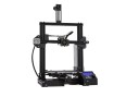
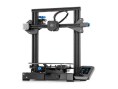
Готов к печати
Готов к печати из коробки
LCD 0.7/1.75 мм
OLED, 0.6/1.75мм, USB
V3.00
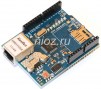
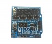
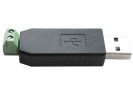
Wiznet W5100 Arduino Shield
v5
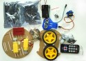
Комплект для сборки
1л
Boscam 200мВт, 5,8Ггц
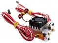
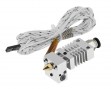
Химера, e3d
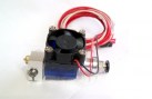
Печатающая головка 1,75мм 0,4мм
Длинный
Короткий
Двойная печатающая головка 1,75мм 0,4мм
10DOF
APM2.6 mavlink
USB
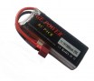
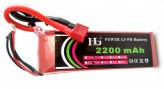
11.1V, 20C
11.1V, 25C
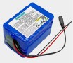
Литиевый аккумулятор
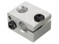
Heat block v6
картриджный тип термистора
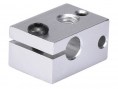
Heat block Volcano
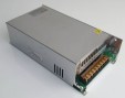
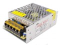
Выходные параметры: 24 В, 600 Вт.
12В 20А
12В 30А
12В 5А
24В 15А
170
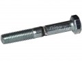
Hobbed bolt
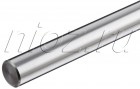
Цена за 10мм (резка бесплатная)
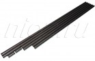
Отрезок 400мм
10мм (резка в размер)
2х400мм, 2х350мм, 2х325мм
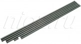
2х420мм, 2х405мм, 2х350мм, 1х20мм
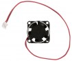
25х25x10мм
30х30х10мм
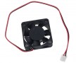
40х40x10мм